Grampo Tipo C - C Cl. What does s-class mean for mercedes Taller del automóvil chapa y pintura en málaga.

Assembly And Details Machine Drawing Pdf
See also block-statistics and the latest 100 blocks.
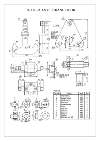
. Problem 164 Working drawing metric PARTS LIST. 1 1 C-frame CS. 10 individual solid 3D parts.
1010 Avenue of the Moon New York NY 10018 US. 3D Inventor 2014 assembly 2D DWG files complete set of documentation zip file 77MB main assembly contains. C-Clamp Assembly Screw Swivel Details of.
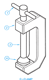
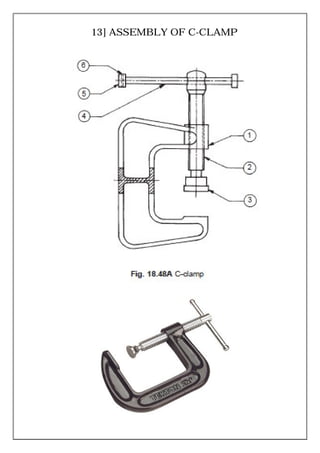
2D Inventor assembly DWG drawings 2 sheets in 1 Inventor DWG files. C-clamp is used to hold a component for further work such as inspection or working on itThe work is clamped between the face of the frame and the pad mounted on the screw. 709x495 Techdrawing Drawing C terminal block 500x405 mounting Drawing 434x618 C terminal block Hpcadd1 700x534 Magnetic ground clamps 1280x720 C terminal 3d Drawing on Autocad 2014 Part 6 Prd By Abdrehman Ahmed 600x400 What are the parts of a terminal block G 266x4 11 A Serie Ip Pergolato C.
No Name of the component quantity Material 1 C-frame 1 Cast-steel grade 26-52 2 Screw 1 Steel 45C8. PDF 29 Kb. It is required to design a C-clamp for holding the jobs on the shop floor limiting dimension of the job are as follows Hmax 150 mm Wmax 150mm The maximum clamping force required to hold the job is 10kN.
C Clamp - C Clamp Dr. C-Clamp Assembly Frame Details of. 3D STEP 3D STL 3D DWF 3 files zip file 35MB.
WEB-023-COMBINED_13pdf Schedule drawing for DN8 ¼ with DN15 ½ branch end T bodies with hygienic clamp ends. These clamps are called C clamps because of their C-shaped frame but are otherwise often called G-clamps or G-cramps because including the screw part they are shaped like an uppercase letter G. 1 5 Jaw Steel 1 4 Pin MS.
PARTS LIST DESCRIPTIONPART NUMBERQTYITEM Project1 - Bottom ring11 Project1 - C body12 Project1 - Pin head13 Project1 - Ring14 Project1 - Shaft15 Project1 - T h SlideShare uses cookies to improve functionality and performance and to provide you with relevant advertising. Item Post Date Author. Item - C Clamp Drawi.
WEB-022-COMBINED_13pdf Schedule drawing for DN8 ¼ T bodies with hygienic clamp ends complete with top works options Page 1 - Body Only Details Page 2 Valve Assembly Details. Laboratory Project Instruction Drawings. All the best C Clamp Drawing 37 collected on this page.
C-Clamp Assembly Frame End Angle Milling. 16 QTY NAME PIN BODY SCREW SWIVEL SR 24 BOTH ENDS 102 72. PDF 27 Kb.
After measuring all other dimensions on the C-clamp as sketched above and discussing the results with the team we conclude that the best length to cut was 38 mm. Name of part Material Notes Q. The DWG-version problem not valid file invalid file drawing not valid cannot open can be solved by the Tip 2869.
CAD Forum - tips tricks. - 22 - 7 Screw rode MS. Size 134kB from 10102011.
Description of Kant Twist Clamp plans PDF and DWG 3D CAD models. Prepare a complete set of working drawings with all of the detail drawings on one sheet and the assembly drawings and parts list on another sheet. 21 TITLE C-CLAMP ASSEMBLY DRAWING Ø4.
1 2 Handle MS. Dimensions to indicate range of motion or overall size of assembly for reference purposes. View C-Clamp Assembly Drawing 1of4 1pdf from ENGR 464 at San Francisco State University.
C-Clamp Assembly Screw Details of. 1 6 Cap screw MS. What is the cpt assistant used for.
Part Dimension Length 38 mm Height 81 mm Web width 57 mm Flanshing thickness 67 mm Flanshing width 4465 mm 13. Assembly Drawings must have a number of views to show how parts fit together. Mon - Sat 800 - 1800.
C-clamp FEA Analysis ME 341 students are asked to determine the stresses on the inner and outer surface of a C-clamp at a point on the curved section and the straight section of the clamp. Section views to show how parts fit and to eliminate hidden detail. Assemble the following parts and Draw full sectional view of the assembly for the following.
2200-60 Sheet 1 Sheet 2 Sheet 3-911228. View C-Clamp-Assembly-Drawing-3of4pdf from ENGR 464 at San Francisco State University. STEP IGES Rendering August 28th 2019 C-Clamp 3 by Mitch Pomerantz.
Go to Article 3D CAD Models - C-clamp PALADIN_C-Clamp-Pole_IM401-P-4 - Paladin Healthcare GN 855 - C-Clamps JW Winco GN 855 - C-Clamps Ganter. How to make thors hammer in real life. C clamp assembly drawing C clamp assembly drawing pdf.
PDF 19 Kb. Use multiview projection for view layout. C Clamp Assembly - C.
4105 2 4 3 17981 C-CLAMP ASSEMBLY 7 1 NO. By Ahmed ElPrince. Files 33 C CLAMP ASSEMBLY all parts Renderings Folder March 23rd 2014 c clamp assembly ggif gif April 6th 2016 c clamp picpdf pdf April 14th 2014.
Are mandrills bigger than baboons. The results are then compared to the solution found using TK Solver. Nintendo switch oled bumper case.
The following details the steps necessary to compute the stresses using FEA in SolidWorks. This video make by Vishwakarma Engineering Drawing Classes Bhilai Nagar. C-Clamps 4in and 3in.
Assembly Drawings must provide sufficient information to enable the assembly of a component. 1 3 Collar MS. Make hole for C-Clamp in Counter Tops.
SOLIDWORKS 2017 STEP IGES Rendering July 26th 2019 Vice Grip Locking C-clamp. The clamp is manually operated fSr. Malicious pdf generator github.
3600 Ø36 Ø20 2610 Ø32 M8 2X45 20 Ø10 6 12 Ø16 976 2 JAW SCALE.
Assembly And Details
Working Drawing Metric Assembly Name C Clamp Specif Chegg Com

Assembly Drawing Of C Clamp Youtube
Assembly And Details Machine Drawing Pdf

G Clamp Pdf Engineering Science And Technology

Pin Em T

C Clamp Assembly

C Clamp Assembly All Parts 3d Cad Model Library Grabcad
0 comments
Post a Comment